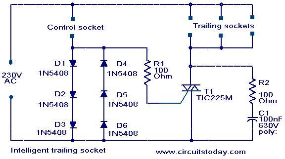
Description.
This is a very simple yet effective circuit in which the equipments connected at the so called trailing sockets will run only if the equipment connected at the control socket is switched on. For example, let’s connect a motor is connected to the control socket and a lamp is connected at the trailing socket. The lamp will glow only when the motor is running.
When the load connected at the control circuit is switched on, the load current flows through the diodes and as a result there will a voltage drop across the diodes. This voltage drop is sufficient enough to switch on the sensitive triac T1 and the equipments connected at the trailing sockets gets power supply. The components R2 and C1 forms a snubber circuit which protects the triac from transient fluctuations.
Almost all equipments like motors, drills, blenders, fan, old TV, radio, amplifiers etc can be connected at the control socket. In case of modern TV, computers, amplifiers, etc the power switch does not completely isolate the equipment and the equipment will draw a small amount of current in the standby mode which is sufficient enough to trigger the triac . Such equipments cannot be used on the control socket because it makes the trailing equipments ON even if the control equipment is OFF.
Circuit diagram with Parts list.

Notes.
- Assemble the circuit on a good quality PCB.
- The triac T1 must be a 600V, 8A, high sensitive gate type like TIC 225M.
- Maxim load that can be connected at the trailing socket is 1000W.
- Fit the triac with a heat sink.
- Take at most care while handling this circuit as it is connected to 230V AC.

2 Comments
Good day,
The specified diodes D1-D6 are rated at 3.0A. Does this mean that the appliance connected to the Control Socket can’t draw more than 3.0A ?
could you please say the power dissipation of the resistors?